PrismPoint revolutionizes surveying with its innovative self-leveling platform for survey prisms.
Why it exists?
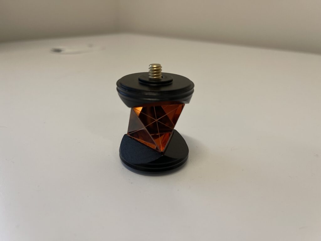
Traditionally, in construction and surveying, prisms play a vital role by reflecting light from Total stations to ensure precise measurements of physical areas. Here’s an example of such a prism. However, maintaining the prism’s level throughout the process is essential for accuracy, a task previously undertaken manually by workers monitoring the level bubble on the prism’s shaft. Enter PrismPoint, a game-changer in surveying technology.
How it works?
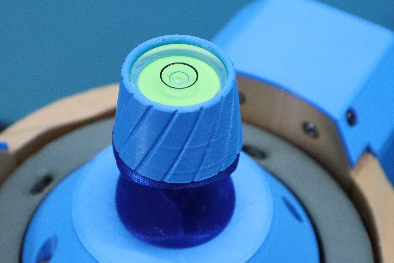
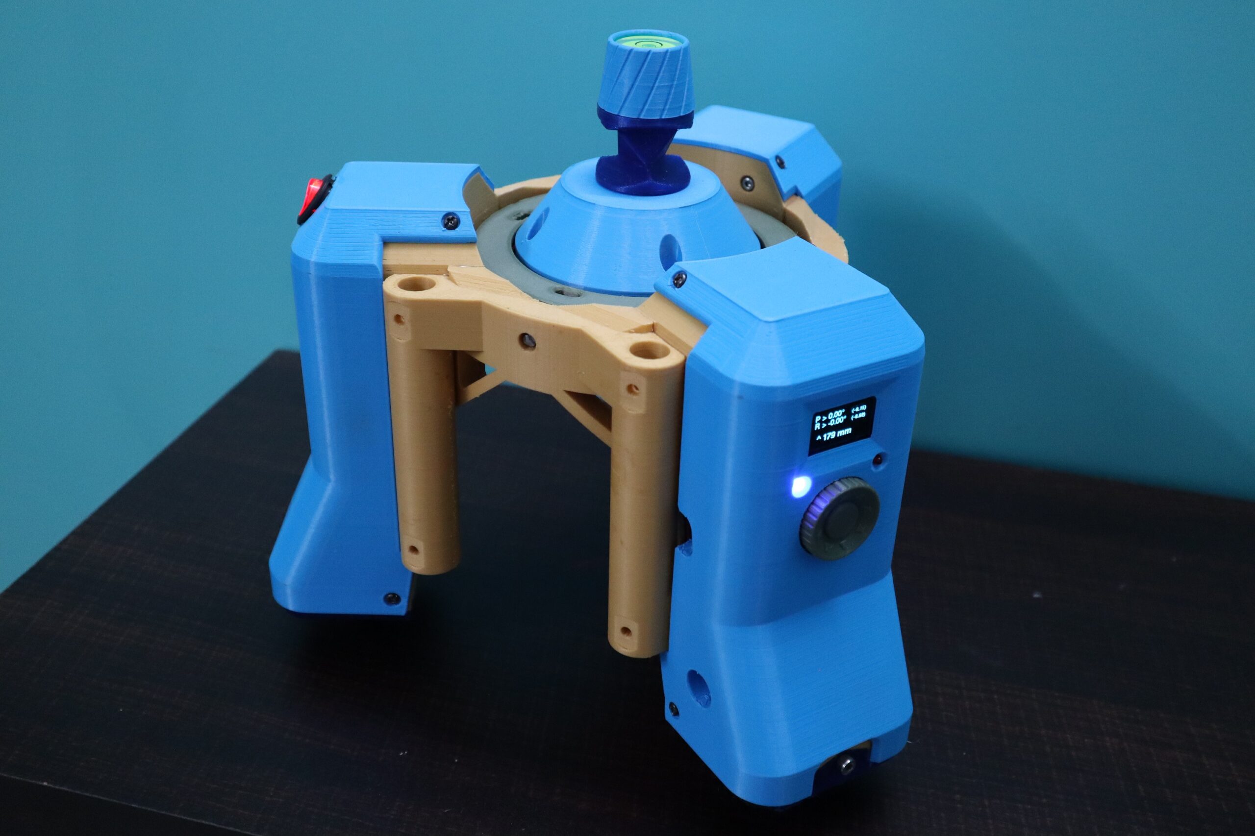
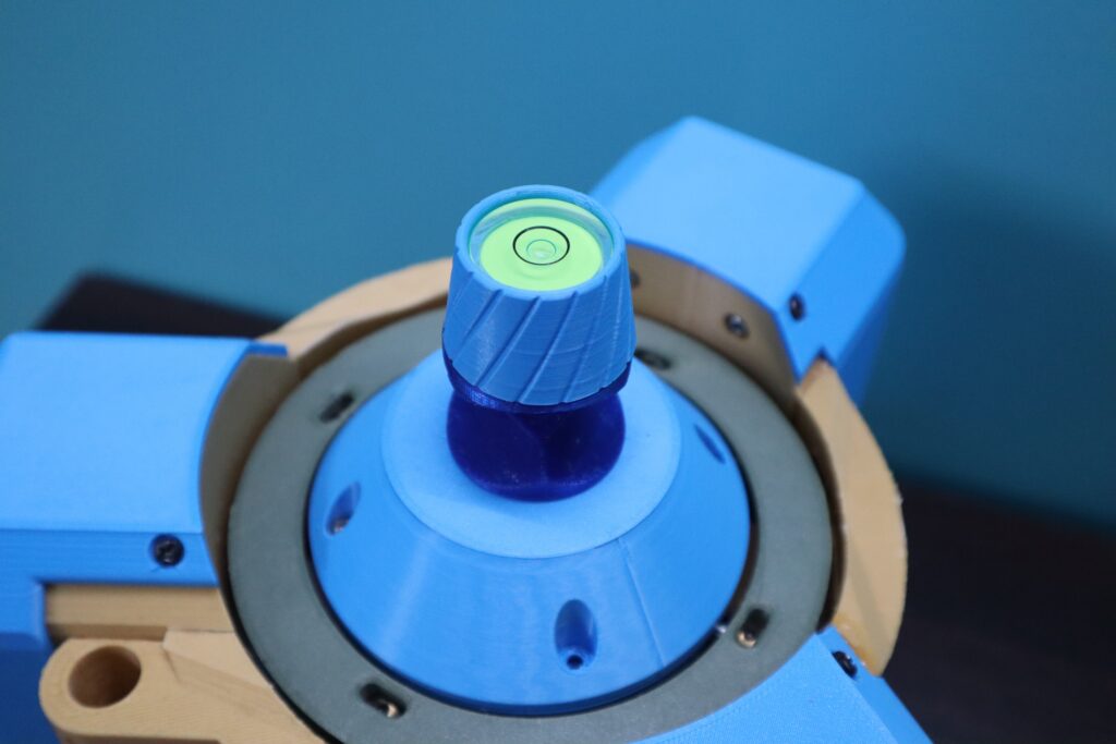
At the center of the PrismPoint, there’s a bolt designed to hold any survey prism. A 2D spirit level is then screwed on top of the prism to indicate whether it is properly leveled.
When the device is powered on by flipping the switch, it boots up and the prism jumps right up and the platform immediately begins leveling the prism by adjusting the platform to align with the ground. The OLED display shows the tilt angles on the roll and pitch axes, quickly converging toward 0.00 degrees and maintaining stability.
As PrismPoint moves over uneven surfaces, it actively stabilizes the prism, keeping it precisely at 0.00 degrees on both axes.
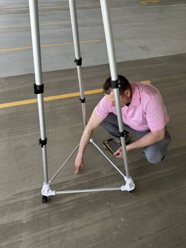
In a surveying scenario where PrismPoint is used with a Total Station (a standard surveying instrument), precise height measurement of the prism from the ground is also essential. To facilitate this, PrismPoint features a laser pointer that projects directly below the prism onto the ground. This helps the operator accurately position the device at the desired location and determine the exact height from that reference point. The OLED display along with tilt angles also shows the measured height.
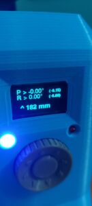
The device also provides an intuitive UI through the OLED display and a dial interface. The operator can calibrate the inertial sensors and adjust the offsets in tilt angles and height from the menu styled interface.
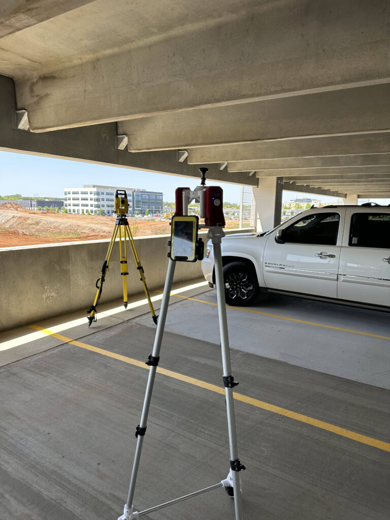
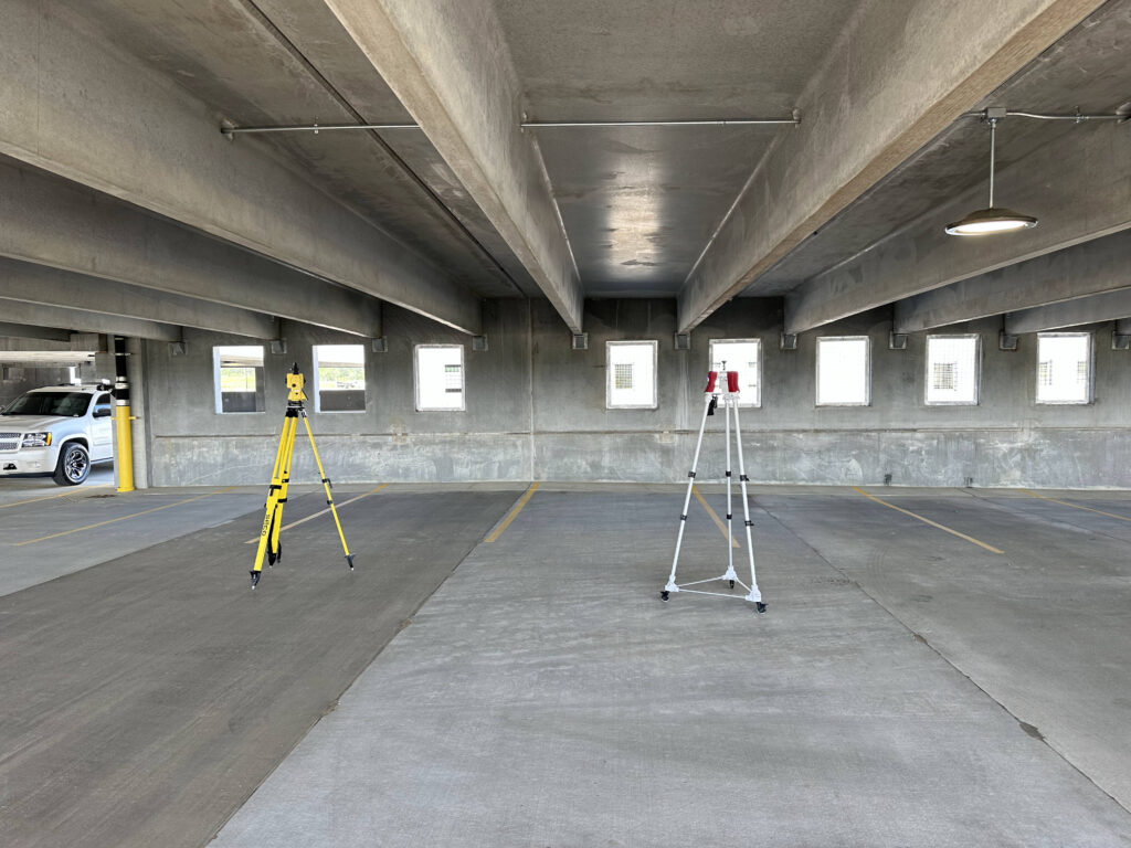
The PrismPoint is designed to be mounted on an extendable, tripod-style wheeled platform. Here’s a glimpse of PrismPoint during actual field testing. The operator can also attach a field tablet to PrismPoint, allowing them to monitor the survey status in real time while the device automatically stabilizes the prism.
What’s Inside?
PrismPoint is a robotic system similar to camera gimbals but designed for higher accuracy in leveling rather than speed. We will go through its mechanical and electronic components in detail.
Electronics
PrismPoint is developed over ESP32 microcontroller. Its basically a dual stepper motor controller that levels the roll and pitch angles of the platform. It makes use of complex sensor fusion algorithms to track the motion and orientation of the device with the help of inertial measurement MEMS systems such as Accelerometer, Gyroscope and Magnetometer.
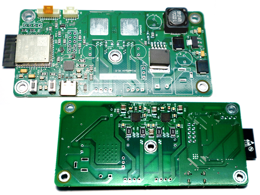
The Main Board PCB has the ESP32 WROOM module and motor drivers used are the TMC2209 for driving two NEMA17 motors. The main board can be powered directly by USB C power adapters. It also has onboard 5V switching regulator which can take up to 18V DC as power Input. The board also has 3.3V linear regulator to power the ESP32. It has CP2012 as USB to Serial Interface.
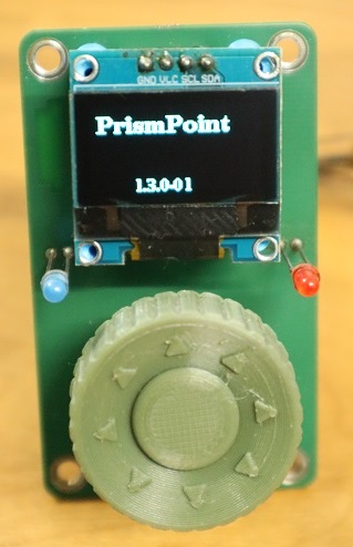
The UI board consist of the 1.3 inch OLED display and a rotary knob switch with a couple of LED’s to show various states of the device.
Sensors
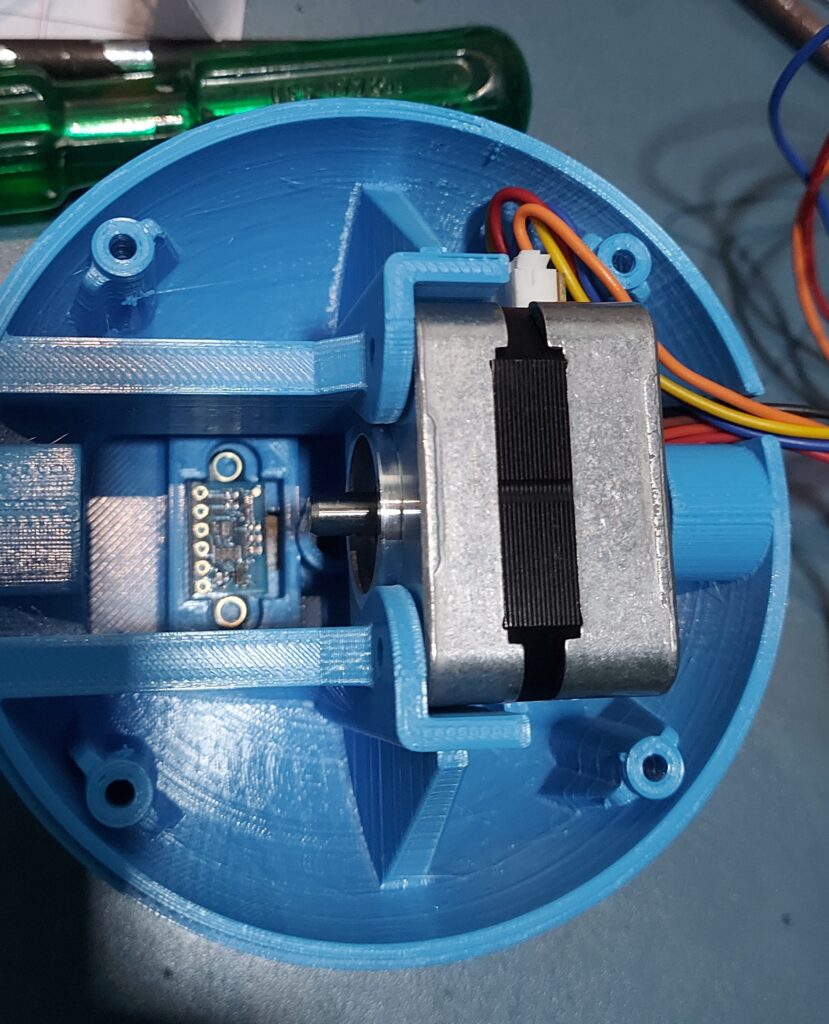
I used the VL53L3CX ToF sensor for height measurement, ISM330DHCX 3D accelerometer and gyroscope and MMC5983MA 3D magnetometer for inertial measurements. I used these in module form to speed up the development.
Mechanical
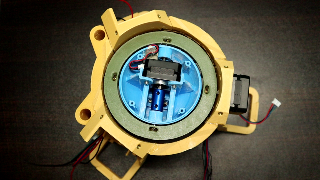
The mechanism of PrismPoint is all 3D printed using a standard FDM 3D printer. The mechanism has three main parts, the main body part was divided into 3 parts which could be press fitted to make it printable on the standard ender 3 printer.
The center most part is the platform for the prism which is to be levelled. This part also contains all the sensors and the laser pointer. one of the stepper motor that controls the pitch angle also sits inside this center part.
The outer rings part holds the center part while also allowing its rotation in the opposite axis (roll axis)
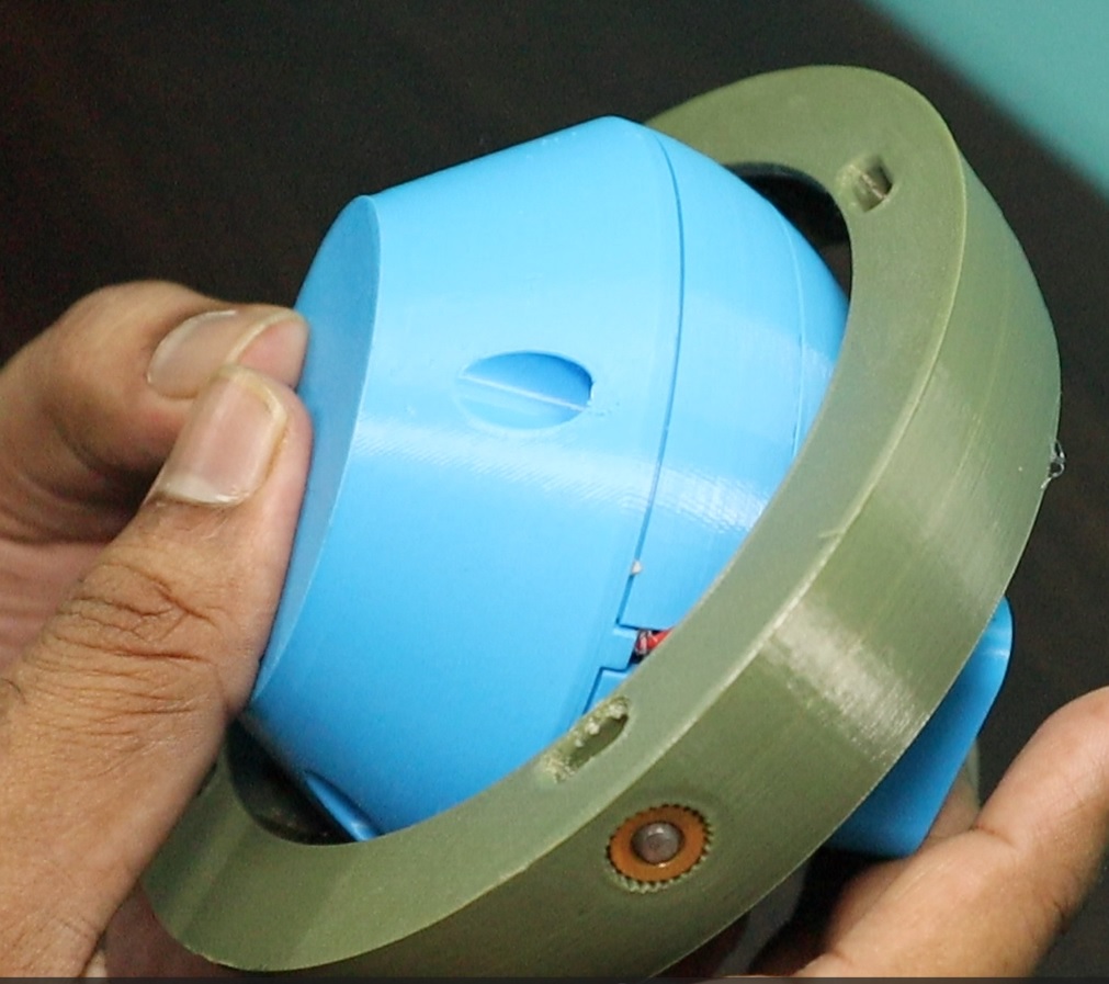
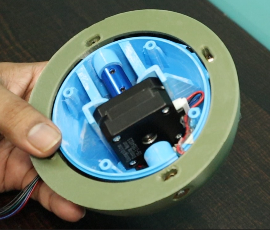
The outer ring then fits into the main body part. All these rotating connections are supported by ball bearings and steel rods.
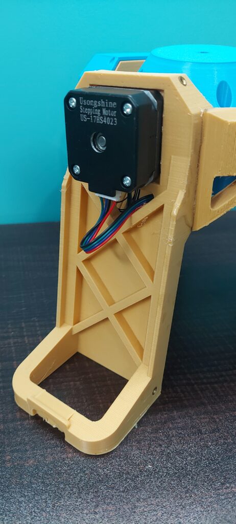
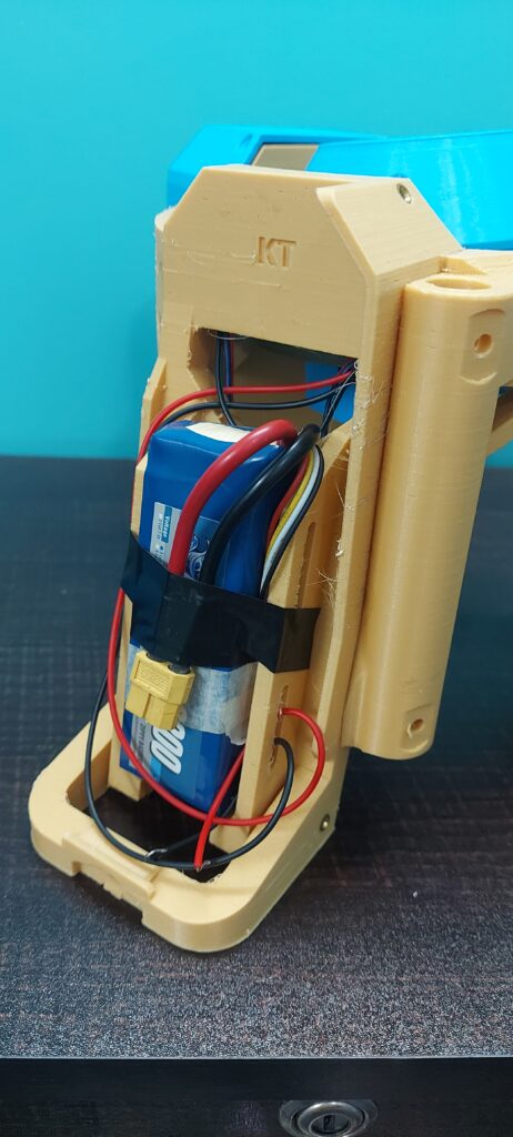
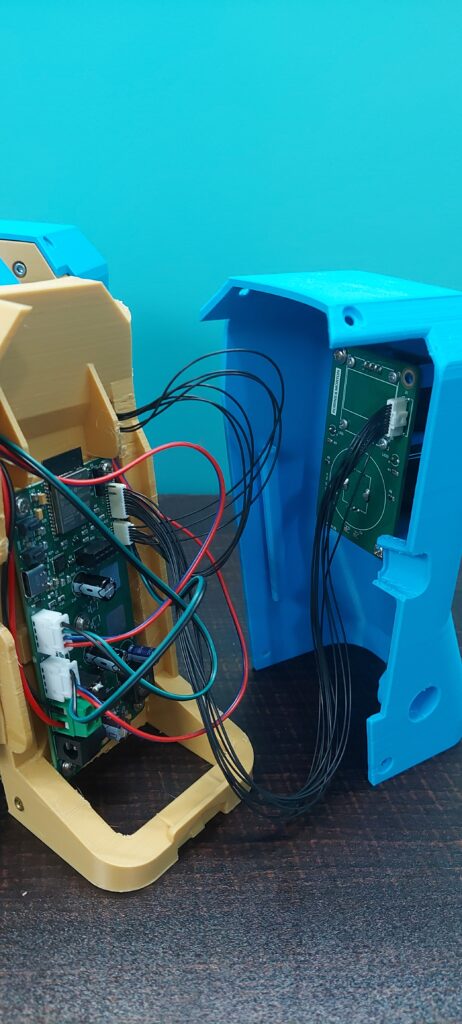
The main PCB and UI PCB are fitted on one of the legs of the body part. on the other two legs, the stepper motor and the battery are fitted.
Firmware
The ESP32 firmware of the PrismPoint has been developed based on freeRTOS and Arduino combined approach. This approach avoids rewriting lots of boilerplate code usually required in the ESP-IDF approach and speeds up the development. The firmware on the higher level has following major functions/taks;
- Inertial sensor reading and preprocessing.
- Sensor Fusion.
- PID controller.
- Stepper Motor Driver.
- Height Measurement and processing.
- Display Driver.
- UI and calibration functions.